Daqscribe — The Ethernet Recorder Company
Development Tools

FPGA + RFSoC Ethernet-based system development tools

Bringing up an RFSoC design means proving what actually left the device. At these rates the only honest answer comes off the wire — so these tools instrument the Ethernet link itself, capture every packet on it, and play the capture back when you need to reproduce a result.

RFSoC (FPGA)

One device, RF to software

Radio Frequency System-on-Chip is the latest defense-grade product from Xilinx. Zynq® UltraScale+™ RFSoC effectively integrates RF front-end and multiprocessing technologies into a powerful monolithic device package.

That integration is what makes the part attractive and what makes it hard to observe: the RF front end, the FPGA fabric and the ARM cores all sit inside one package, so the first place a signal becomes independently measurable is the Ethernet link leaving it.
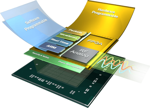
Cutaway illustration of a Zynq UltraScale+ RFSoC package, showing the hardware-programmable FPGA and RF Analog layers alongside the software-programmable ARM, Real Time and Waveform layers, over a security, safety and power-management substrate.
Hardware-programmable and software-programmable domains in one package. Source: Xilinx, now part of AMD. All trademarks and brand names are the property of their respective owners and do not constitute an endorsement.
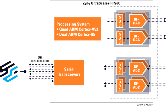
Block diagram of a Zynq UltraScale+ RFSoC. Inside the device, a Processing System with quad ARM Cortex-A53 and dual ARM Cortex-R5 cores sits alongside serial transceivers carrying CPRI, 10GbE, 40GbE and 100GbE off-chip toward the Daqscribe mark on the left. On the right, digital up-converters feed RF-DAC outputs and RF-ADC inputs feed digital down-converters.
Inside the device: ADCs and DACs on one side, ARM cores and FPGA fabric in the middle, and serial transceivers carrying CPRI and 10/40/100GbE off-chip. That left edge is where a recorder attaches — everything upstream of it is inside a package you cannot probe. Diagram courtesy of Xilinx.
Applications

FPGA + RFSoC and Daqscribe recorders for intelligent radio applications

Different domains, one capture problem underneath: a device emitting more data per second than any host can casually absorb.

Wireless comms

  • Remote Radio
  • 5G Baseband
  • μ/mmWave
  • MIMO
  • O-RAN

Cable TV access

  • R-PHY node
  • DOCSIS 3.1

Radar

  • Phased Array Radar
  • Synthetic Aperture Radar
  • 3D Radar

Autonomous vehicle

  • LiDAR

IoT

  • i.e., MIPI® DSI

Test & Measurement

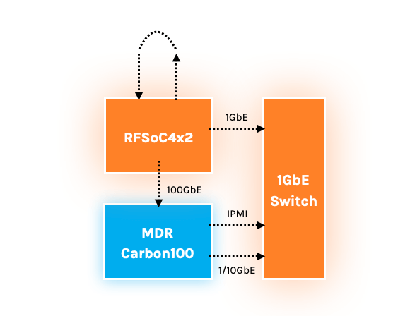
Topology diagram: an RFSoC4x2 board sends captured data over a 100GbE link to an MDR CARBON100 recorder. Both connect to a 1GbE switch — the RFSoC4x2 over 1GbE, the CARBON100 over IPMI and 1/10GbE — for command and control.
A working setup: RFSoC4x2 streaming over 100GbE into an MDR CARBON100, with a 1GbE switch carrying command, control and IPMI.
Smart packet capture

Timestamped at the port, processed in the FPGA

Packets are stamped as they arrive and decoded, filtered, sliced and merged in hardware before they ever reach host memory — which is what keeps capture lossless at line rate.
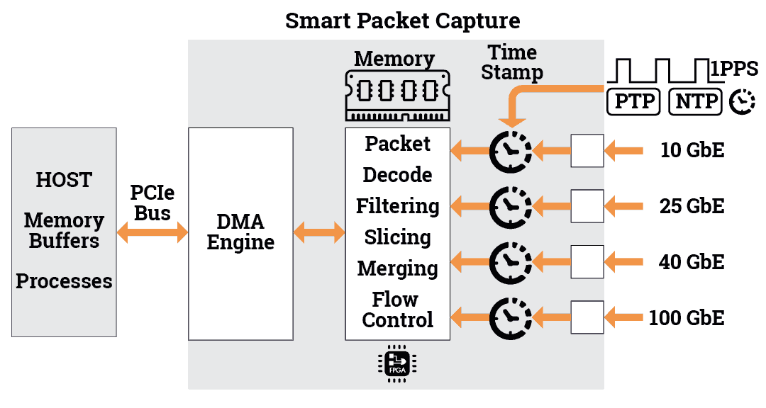
Smart packet capture block diagram: 10, 25, 40 and 100 GbE inputs each pass a timestamp clock fed by PTP, NTP and 1PPS, into an FPGA block performing packet decode, filtering, slicing, merging and flow control against onboard memory, then over a DMA engine and PCIe bus into host memory buffers and processes.
Capture path from port to host. Timestamping happens before any processing, so a packet's arrival time survives everything done to it downstream.
What you can watch

Instrumentation, not inference

L2 monitoring tool

  • Port statistics / RMON counters, Rx – Tx
  • Checksum error counters
  • Packet decode counters
  • Drop counters
  • IPF table counters

Sensor monitoring

  • PPS statistics
  • IEEE 1588 PTP

Capture, record and playback using simple command line utilities. Playback once or loop-back from a recorded file back to a port. nStudio™ software provides full-blown record/playback features for long-term operations.
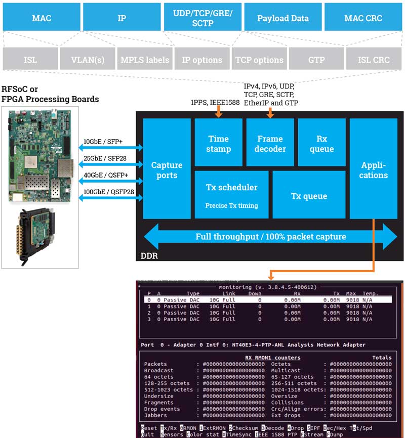
Daqscribe Ethernet recorder architecture with RFSoC or FPGA processing boards on the left, connected over 10GbE SFP+, 25GbE SFP28, 40GbE QSFP+ and 100GbE QSFP28 links into the recorder's capture ports. Inside, timestamp, frame decoder and Rx queue blocks handle receive, with Tx scheduler and Tx queue providing precise transmit timing, at full throughput and 100% packet capture. Above, the decoded header stack spans MAC, IP, UDP/TCP/GRE/SCTP, payload data and MAC CRC, with optional ISL, VLAN, MPLS, IP options, TCP options and GTP layers. Below, a screenshot of the port monitoring utility showing per-port link state and RMON counters.
From RFSoC or FPGA processing board to capture port: the link options, the header layers the recorder decodes, and the operator's port view.
Our Solutions

What ships with it

  • Real-time Ethernet statistics monitoring
  • Protocol-agnostic packet capture
  • A target Ethernet protocol development tools
  • Sustained 100% Ethernet recording performance
  • Playback up to the full link-rate(s)
Record and Compute Flow

Where the data goes once it is on the box

The same platform, twice: the hardware it is built from, then the path a capture actually takes through it.
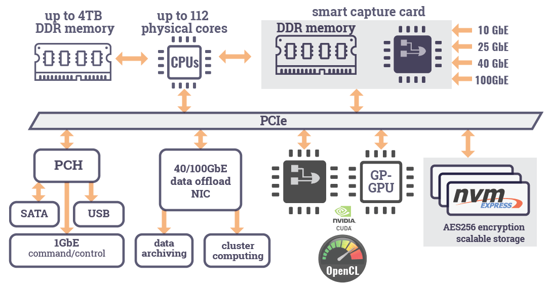
Recorder platform block diagram: a smart capture card taking 10, 25, 40 and 100 GbE inputs into its own DDR memory, connected over PCIe to up to 112 physical CPU cores with up to 4TB of DDR memory, a 40/100GbE data offload NIC feeding data archiving and cluster computing, an FPGA and GP-GPU running CUDA and OpenCL, NVMe storage with AES256 encryption, and a PCH providing SATA, USB and 1GbE command and control.
The platform — capture card, compute, offload and storage on one PCIe fabric.
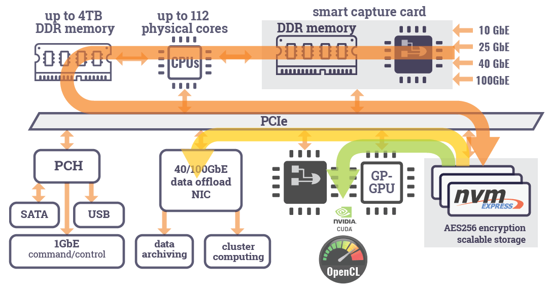
The same recorder platform diagram with the active data path highlighted: capture traffic flows from the smart capture card across PCIe to NVMe storage and to host memory, with branches to the GP-GPU for processing and to the 40/100GbE offload NIC for archiving.
The flow — capture to storage, with branches to the GPU for compute and the NIC for offload.
Application note

Designing a High-Speed EW System with RFSoC and 100GbE Recording

High-speed RFSoC-based EW systems generate massive data streams, requiring efficient real-time recording. The note walks the whole path on real hardware — packetizing ADC samples into UDP, moving them over 100GbE, configuring both ends, and verifying the capture afterwards.
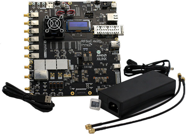
An AMD Xilinx RFSoC 4x2 PYNQ evaluation board with its SMA cables, microSD card and external power supply laid out beside it.
The RFSoC 4x2 evaluation board used in the note.
Ethernet Recorders

Browse our top selection of Ethernet recorders

Every Daqscribe recorder captures Layer 2 at full line rate, whatever the protocol above it. Have questions or need help? Contact us.